Difference between revisions of "Rotators"
m (→Add your rotators: Explain how rotator groups can be used.) |
m (→Add your rotators: Added info. about using Green Heron RT-21) |
||
| Line 38: | Line 38: | ||
[[Image:WtRotatorsControllersAdd.png|center]] | [[Image:WtRotatorsControllersAdd.png|center]] | ||
| − | Select a rotator type from the list, | + | Select a rotator type from the list. If you are using a [http://www.greenheronengineering.com/proddetail.php?prod=RT-21 Green Heron RT-21] control box, select '''Hy-Gain DCU-1'''. |
| + | |||
| + | Next, enter all the values applicable to the antennas turned by that rotator, for example: | ||
[[Image:WtRotatorsAddRotator.png|center]] | [[Image:WtRotatorsAddRotator.png|center]] | ||
Revision as of 02:53, 7 September 2013
Automated rotators may be controlled by an external application provided as part of the Win-Test package called wtRotators. This program (wtRotators) communicates directly with the rotator hardware via serial ports, not Win-Test. Win-Test just sends broadcast messages to wtRotators.
Configuring wtRotators (single-op environment)
The reasoning behind using a separate program for controlling rotators was to be able to have only one PC per rotator controller in a multi-op environment, rather than having to switch rotator control between different PCs. But, in a single PC environment, no network is required.
Configuration of wtRotators is straightforward, very similar to configuring wtDxTelnet. It only needs to be done once. This section explains how to setup wtRotators and Win-Test for use in a single-op environment, with both wtRotators and Win-Test running on the same computer. There are further instructions below describing what has to be done in a multi-op environment.
Configuring Win-Test for wtRotators
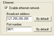
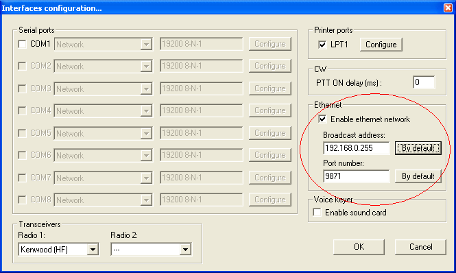
First, open the Configure Interfaces window in Win-Test via Options | Configure interfaces..., or just type the text command SETUP and press [Enter]. Check the box labeled Enable ethernet network and ensure that it looks like the following:
When running both programs on a single PC, use the "loopback" broadcast IP address, 127.255.255.255. No Ethernet connection is required when specifying this special address; it is internal to the machine and always present.
Press [OK]. This is the only change of configuration you'll have to make in Win-Test itself. You can also open the rotators window via Windows | Rotators.
Configuring wtRotators (single PC, no network)
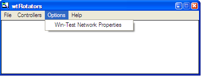
Start wtRotators (in Windows, Start | Programs | Win-Test | wtRotators, or use the pop-up menu in the Win-Test Rotators Window. From the wtRotators menu, select Options | Win-Test Network Properties.
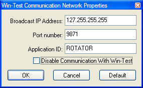
Edit all the values so that they look exactly like this:
These options may well be greyed out by default, in which case be sure to uncheck the box labeled Disable communication with Win-Test, and then you will be able to edit everything. Use the same loopback broadcast address and port number that you specified in Win-Test, as shown above.
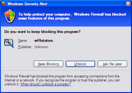
Press [OK]. You may then see a security alert from Windows about wtRotators:
This is normal. Press [Unblock] and you should never see it again.
Note that wtRotators must always be running in the background if you want automated control of your rotators via Win-Test. Like wtDxTelnet, wtRotators can be started and stopped automatically. See Windows | Rotators.
Add your rotators
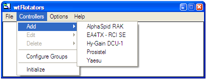
From the wtRotators menu, choose Controllers | Add.
Select a rotator type from the list. If you are using a Green Heron RT-21 control box, select Hy-Gain DCU-1.
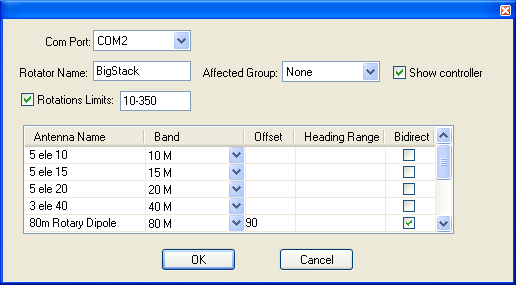
Next, enter all the values applicable to the antennas turned by that rotator, for example:
A quick description of the various settings here. Most of the fields in this window have a "tool tip"; just hover the mouse pointer over the field to display quick pop-up help text about the field.
- Com Port - Select COM1, COM2, etc., whatever serial port is connected to the specified rotator. Baud rate and other settings are determined automatically by the previously-selected rotator type. To disable rotator control, select None.
- Rotator Name - The rotator name you choose will appear in the wtRotators messages window, and at the top of the small controller window.
- Affected Group - Select a group name or select None. The default group names are Group #1 to Group #18, but you can edit these group names via Controllers | Configure Groups. You can put several antennas into a group to turn them all at once. This is useful for stacked antennas which are on separate rotors. In WT, you can then turn the "stack" (all rotors will be turned to the target azimuth), or you can turn them independently (for example, both antennas beamed to two different directions).
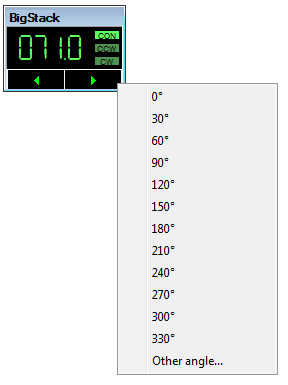
- Show controller - When this box is checked, wtRotators will launch a small "controller window" with buttons that may be used to manually turn the rotator. It also has a pop-up menu for quickly selecting beam headings from 0 to 330° in 30° increments or any specific heading (right click to view the pop-up).
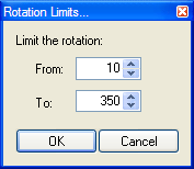
- Rotation limits - Click to display pop-up window where you can enter the range of values supported by this rotator. Any heading outside the range will be translated to the nearest limit. [Q: How does one specify that 170 to 190° are "out of range"? --Ed.]
- Antenna Name - Choose any name for your antennas. Each antenna must have a unique name.
- Band - Operating band. Win-Test turns the proper rotator based on the operating band of the active radio. For multiband antennas, create several entries as shown above.
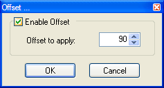
- Offset - Offset to apply to the read angle if the antenna is skewed from the rotator indication. Click to enter a value between 0 and 360°. For example, if you have a rotary dipole in line with the booms of your Yagis, use 90° as shown in the example. Be sure to check Enable Offset as shown. For "negative" offsets, like "-25°", use the equivalent value, 335°.
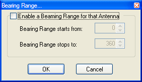
- Heading Range - Click to specify a range of beam heading values supported by this antenna. If the antenna is to be used for all directions, leave this column blank by unchecking Enable a Beaming Range for that Antenna. [Q: How to specify a range that excludes 170 to 190°? --Ed.]
- Bidirect - Check this box when using a bi-directional antenna, such as a dipole. Win-Test will automatically move the rotator to the nearest usable beam heading.
Press [OK] to save all changes, or [Cancel] to start over.
Testing the configuration
Once you have setup both Win-Test and wtRotators, it is time to verify that you can control the rotator from within Win-Test.
In Win-Test, enter either a callsign or a beam heading (0 to 360°) on the last line of the log entry window, and press [Ctrl]+[F12] to rotate to that heading. When entering a callsign or prefix, use [Alt]+[F12] for long (or "alternate") path. You can also move the cursor up to a previous QSO and press either key to rotate to the heading for that callsign. Callsign prefixes within your own country cannot be used to rotate the beam.
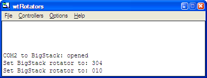
You should immediately see a message in the wtRotators window such as the following:
and the rotator should turn to the indicated heading.
If you see no messages in the wtRotators window, it means Win-Test and wtRotators are not communicating properly. Verify that both are using the same broadcast IP address and port number, and that "Disable communications with Win-Test" is not checked, and that your firewall is not blocking the port.
Editing the rotator configuration
From the wtRotators menu, choose Controllers | Edit or Controllers | Delete.
Adding additional rotators
From the wtRotators menu, choose Controllers | Add and repeat the procedure described above for each rotator that you want to support.
Initializing rotator communications
wtRotators automatically re-initializes communications with the rotator when any change is made. If the rotator is temporarily disconnected or powered off, or if wtRotators is no longer turning the rotator even though all the normal messages are displayed, from the wtRotators menu, select Controllers | Initialize and wtRotators will reopen the specified COM port and attempt to re-establish communications with the rotator controller.
Configuring wtRotators (multi-op environment)
The above guide covers setting up Win-Test and wtRotators in a single-op environment and thankfully the only difference between the two configurations is the networking set-up in wtRotators.
Obtaining your network broadcast address
In order to configure wtRotators correctly, you need to know the IP broadcast address you have set in Win-Test for the network. Simply open the Configure Interfaces window in Win-Test via Options | Configure interfaces..., or just type the text command SETUP and press [Enter]. Press the [By default] button to have Win-Test automatically calculate the broadcast address based on your PC's current IP address.
The broadcast address is found as follows:
So, in this above example, the broadcast address is 192.168.0.255. Use this same broadcast address and port number in wtRotators, in wtDxTelnet, and in all networked PCs. Just press the [Default] button in wtRotators, and it will calculate the same broadcast value as Win-Test, no need to write anything down.
Configuring wtRotators (multiple PCs in a network)
The advantage of wtRotators in a multi-op environment is that you only require one connection to a rotator control box, all networked PCs will be able to control that rotator, based on operating band.
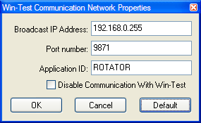
Follow the steps above, for configuring wtRotators in a single-op environment, but the network properties will be different. Go to the Options|Win-Test Network Properties menu in wtRotators.
Use the following details:
- Broadcast IP address - It is very important that you get the address absolutely correct for the rotator data to be propagated across the network. It must match the broadcast address which you have specified in Win-Test's network properties in the previous step. Using the example above, in this instance, the broadcast IP address would be 192.168.0.255. Just press the [Default] button shown above, and wtRotators will calculate the same default broadcast address as Win-Test's [By default] button.
- Port number - Can usually be left as-is. Again, it must match what has been specified in Win-Test. The same port number can be used for both wtDxtelnet and wtRotators. The default port number is 9871. Use 9871 unless you have already changed the port number (and thus you should know what you're doing and thus you should know the port number).
- Application ID - Can also be left as ROTATOR.
Click [OK], and you have successfully configured both Win-Test and wtRotators. You should now test the configuration as described above.
Add your rotators
Add your rotators as described above. Keep in mind that any rotator can be turned by any operator, so take care to limit the bands and beam headings covered by each rotator.
