Difference between revisions of "Interfaces"
m (→COM-port CW keying: Replace COM port keying circuit with improved PTT and CW schematic, with pin numbers) |
|||
| (22 intermediate revisions by 4 users not shown) | |||
| Line 3: | Line 3: | ||
== Interface configuration == | == Interface configuration == | ||
| − | The interface configuration window can be opened by clicking on <code>Options->Configure Interfaces</code> menu in the main Win-Test | + | The [[Menu:Options#Configure_interfaces...|interface configuration window]] can be opened by clicking on <code>Options->Configure Interfaces</code> menu in the main Win-Test window, or via the text command '''<tt>SETUP</tt>'''. |
| − | + | === Radio configuration === | |
| + | At the bottom of the window there is a "Transceivers" section which includes two drop-down lists where you set your radio type ('''Radio 1''' and '''Radio 2'''). First, choose your rig make and model from the appropriate list. Please note that there is only one "Kenwood" entry in the list because all Kenwood rigs use a common protocol. | ||
| − | + | On the left hand side of the window, you will see a list of COM ports (only available COM ports on your system will be selectable). After you have chosen the manufacturer and/or model of your rig, check the box corresponding to the COM port to which your radio is connected. For example: | |
| − | + | [[Image:Interfaces.png|frame|center|COM port configuration]] | |
| − | If you are | + | Upon checking the box, you will notice that the adjacent drop-down box will now be enabled. You ''must'' choose '''Radio 1''' or '''Radio 2''' from this drop-down list. You must also '''ensure that the port (baud rate) settings are correct for your radio'''. |
| + | |||
| + | By default, the settings of 19200 8-N-1 will be configured, which is probably incorrect for your radio. Click on the adjacent '''<tt>[Configure...]</tt>''' button to display the [[Menu:Options#Serial_Ports|COM port properties dialog]]: | ||
| + | |||
| + | [[Image:com1-properties.png|frame|center|COM port configuration for Radio1 / Radio2]] | ||
| + | |||
| + | If you are not sure about the baud rate settings for your transceiver, press the '''<code>[default settings]</code>''' button to change all values to the known hardware defaults for the selected radio. | ||
| + | |||
| + | There is also a list of known working settings for common contest radios located in the [[Supported_rigs|Supported rigs]] chapter. | ||
== Configuring other interfaces == | == Configuring other interfaces == | ||
| − | As you may well have noticed by this stage, a variety of other interfaces can also be enabled from the <code>Configure Interfaces</code> dialog box. It is just a simple case of ticking the relevant COM port and choosing said device from the drop-down list. Examples include TNCs, SO2R switching boxes (e.g. EZmaster, W5XD Keyer, etc) | + | As you may well have noticed by this stage, a variety of other interfaces can also be enabled from the <code>Configure Interfaces</code> dialog box. It is just a simple case of ticking the relevant COM port and choosing said device from the drop-down list. Examples include TNCs, SO2R switching boxes (e.g. [[SO2R/EZMaster/Setup|EZmaster]], [[SO2R/MK2R/Setup|microHAM MK2R]], WinKey, W5XD Keyer, etc.). For everything not on the list, you can choose <code>Other interface...</code> and configure the port settings yourself - for example, COM port CW interface (see below). |
=== COM-port CW keying === | === COM-port CW keying === | ||
| − | If you have a simple transistor-based COM port CW interface (see below), you can enable this by again choosing the corresponding COM port, and selecting <code>Other interface...</code> from the drop-down list. Clicking on the <code>Configure</code> button will | + | If you have a simple transistor-based COM port CW interface (see below), you can enable this by again choosing the corresponding COM port, and selecting <code>Other interface...</code> from the drop-down list. Clicking on the <code>Configure</code> button will display the [[Menu:Options#Serial_Ports|COM Port Properties dialog]] including a drop-down list of options for DTR (pin 4) and RTS (pin 7) on |
| − | a | + | a DE9 connector (pins 20 and 4 on a DB25). Connect the emitter of the NPN transistor to signal ground, pin 5 on DE9 (pin 7 on DB25). |
| + | |||
| + | ''Be sure to select '''DTR: CW''' and '''RTS: PTT''' in the COM port Properties under Interface Configuration.'' | ||
| − | [[Image: | + | [[Image:COM_Port_CW_PTT_Circuit.png|center|frame|Simple COM port CW and PTT interface for DE-9 9-pin serial connector or USB-to-Serial adapter]] |
| − | This interface was designed for K1EA's CT and is still in use today with Win-Test | + | This interface was designed for K1EA's CT and is still in use today with Win-Test. |
=== LPT-port CW keying === | === LPT-port CW keying === | ||
| − | Likewise, if you have | + | Likewise, if you have an LPT (parallel) port CW interface (see schematics below), you can enable it by checking the box next to 'LPT' in the [[Menu:Options#Configure_interfaces...|Configure interfaces dialog]]. Clicking on the <code>[Configure]</code> button in the Printer Ports section will display the [[Menu:Options#Printer_Ports|Printer Ports dialog]]. At the very bottom, you can enable CW and PTT on pin 17 and 16 respectively. ''Ensure this is checked.'' |
| − | + | {{wbox|WARNING|In order for LPT keying to function correctly under Windows XP, Vista, or 32-bit Windows 7, you will need an additional utility, '''DLPortIO.dll''' installed by Port95NT.exe, obtainable from the Win-Test website. It is a simple process and only needs to be installed/run once. Please [http://download.win-test.com/port95nt.exe click here] to download. For 64-bit Windows 7, use InpOut32.dll as described in [http://lists.f5mzn.org/pipermail/support/2011-May/081094.html this post].}} | |
| − | |||
| − | |||
[[Image:Schema_InterfaceCW.gif|center|frame|Simple LPT port CW interface]] | [[Image:Schema_InterfaceCW.gif|center|frame|Simple LPT port CW interface]] | ||
| Line 38: | Line 47: | ||
=== Digital Voice Keyer === | === Digital Voice Keyer === | ||
| − | The DVK-100 voice keyer was the first computer-controlled voice memory in the contesting world in the early 90s. Later, some equipment manufacturers built voice memories into their radios like Kenwood (TS-850, TS-950 with the | + | The DVK-100 voice keyer was the first computer-controlled voice memory in the contesting world in the early 90s. Later, some equipment manufacturers built voice memories into their radios like Kenwood (TS-850, TS-950 with the DRU2 and DRU3 units respectively - probably others). These devices can be controlled by Win-Test using the following LPT interface. |
[[Image:Schema_InterfaceDVK.gif|center|frame|Simple LPT port DVK interface]] | [[Image:Schema_InterfaceDVK.gif|center|frame|Simple LPT port DVK interface]] | ||
| Line 51: | Line 60: | ||
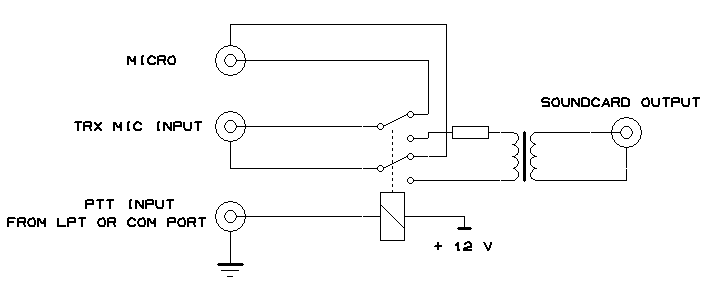
[[Image:Schema_Interface_SoundCard.gif|center|frame|Sound Card Interface]] | [[Image:Schema_Interface_SoundCard.gif|center|frame|Sound Card Interface]] | ||
| − | + | The use of an isolation transformer is recommended both on the output side of the sound card. Of course, you can go without one but first think about the trouble you will encounter when the Line Out port of your sound card gets killed by stray RF or when someone tells you you got hum on your audio in the middle of the contest. | |
| + | |||
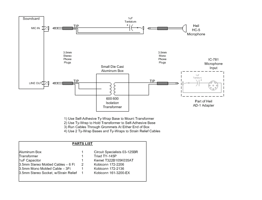
| + | [[Image:SoundcardInterface.gif|center|frame|Sound Card interface kindly provided by W9ZRX. This interface is in use at the K3LR M/M station.]] | ||
W9ZRX has provided this design that comes without a relay to switch Mic input between radio and sound card. Most sound cards allow routing from Mic input to Line Out so that you can control muting Line Out from within Win-Test. Make sure that the Microphone has been enabled as an Input to the Sound Card Mixer. Different Sound Cards set up slightly differently, but most seem to either show the Microphone Input to the Mixer as '''muted''', or the default Mixer Inputs do not include the Microphone until '''enabled'''. | W9ZRX has provided this design that comes without a relay to switch Mic input between radio and sound card. Most sound cards allow routing from Mic input to Line Out so that you can control muting Line Out from within Win-Test. Make sure that the Microphone has been enabled as an Input to the Sound Card Mixer. Different Sound Cards set up slightly differently, but most seem to either show the Microphone Input to the Mixer as '''muted''', or the default Mixer Inputs do not include the Microphone until '''enabled'''. | ||
| − | There are sound cards that do not | + | There are sound cards that do not support this option. The Writelog download site has a [http://www.writelog.com/Downloads/sbrdchk.zip sound card checker] that will help you to determine if you have this problem if it absolutely doesn't work. |
Another way would be to try using the Win-Test PTT output to drive a relay to allow a direct routing between your Mic and the Mic input of your TRX when the PTT output is off. This requires some additional components but better than an external mic to record the DVK messages. | Another way would be to try using the Win-Test PTT output to drive a relay to allow a direct routing between your Mic and the Mic input of your TRX when the PTT output is off. This requires some additional components but better than an external mic to record the DVK messages. | ||
| Line 61: | Line 72: | ||
=== Band Data === | === Band Data === | ||
| − | Win-Test supports filter and antenna switching by supplying Yaesu-standard Band data on pins 2, 7, 8 and 9 of the parallel port. These pins are equivalent to lines A, B, C and D. This feature allows you to automatically control other devices in your station, probably by using a band decoder like the one from [http://www.qth.com/topten/bdecoder.htm Top Ten | + | Win-Test supports filter and antenna switching by supplying Yaesu-standard Band data on pins 2, 7, 8 and 9 of the parallel port. These pins are equivalent to lines A, B, C and D. This feature allows you to automatically control other devices in your station, probably by using a band decoder like the one from [http://www.qth.com/topten/bdecoder.htm Top Ten Devices]. |
{| {{Prettytable_fixed}} | {| {{Prettytable_fixed}} | ||
| Line 85: | Line 96: | ||
|- | |- | ||
| 6 m || 1 || 0 || 1 || 0 | | 6 m || 1 || 0 || 1 || 0 | ||
| + | |- | ||
| + | | 2 m || 1 || 0 || 1 || 1 | ||
| + | |- | ||
| + | | 70 cm || 1 || 1 || 0 || 0 | ||
|- | |- | ||
|} | |} | ||
| Line 93: | Line 108: | ||
=== Headphones Control === | === Headphones Control === | ||
| − | The signals ''Headphones Control'' (called ''RX Focus'' in the MK2R microHAM SO2R interface) is available on LPT, pin 4. This signal allows to control which radio you want to listen to in the headphones. Must be enabled in the LPT Configuration Window. Low = | + | The signals ''Headphones Control'' (called ''RX Focus'' in the MK2R microHAM SO2R interface) is available on LPT, pin 4. This signal allows to control which radio you want to listen to in the headphones. Must be enabled in the LPT Configuration Window. Low = Radio 1, High = Radio 2. |
== See Also == | == See Also == | ||
| Line 99: | Line 114: | ||
=== From the Win-Test manual === | === From the Win-Test manual === | ||
| + | * [[Menu:Options#Configure_interfaces...|Configure interfaces dialog]] | ||
* [[Networking|Networking configuration for multi-ops]] | * [[Networking|Networking configuration for multi-ops]] | ||
| − | * | + | * [[SO2R/EZMaster/Setup|EZMaster setup]] |
| + | * [[SO2R/MK2R/Setup|microHAM MK2R setup]] | ||
=== External sources === | === External sources === | ||
Revision as of 18:37, 7 June 2016
Configuration of interfaces in Win-Test needs only be done once, rather than on a per-contest basis. This means you do not waste time remembering your interface configuration details prior to each contest!
Interface configuration
The interface configuration window can be opened by clicking on Options->Configure Interfaces menu in the main Win-Test window, or via the text command SETUP.
Radio configuration
At the bottom of the window there is a "Transceivers" section which includes two drop-down lists where you set your radio type (Radio 1 and Radio 2). First, choose your rig make and model from the appropriate list. Please note that there is only one "Kenwood" entry in the list because all Kenwood rigs use a common protocol.
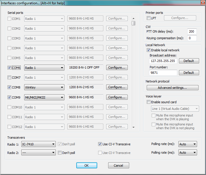
On the left hand side of the window, you will see a list of COM ports (only available COM ports on your system will be selectable). After you have chosen the manufacturer and/or model of your rig, check the box corresponding to the COM port to which your radio is connected. For example:
Upon checking the box, you will notice that the adjacent drop-down box will now be enabled. You must choose Radio 1 or Radio 2 from this drop-down list. You must also ensure that the port (baud rate) settings are correct for your radio.
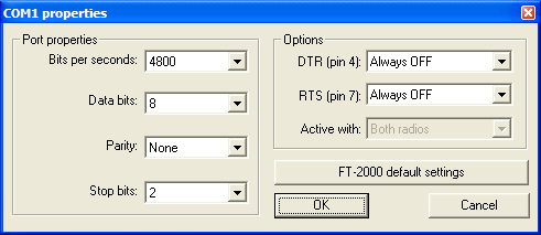
By default, the settings of 19200 8-N-1 will be configured, which is probably incorrect for your radio. Click on the adjacent [Configure...] button to display the COM port properties dialog:
If you are not sure about the baud rate settings for your transceiver, press the [default settings] button to change all values to the known hardware defaults for the selected radio.
There is also a list of known working settings for common contest radios located in the Supported rigs chapter.
Configuring other interfaces
As you may well have noticed by this stage, a variety of other interfaces can also be enabled from the Configure Interfaces dialog box. It is just a simple case of ticking the relevant COM port and choosing said device from the drop-down list. Examples include TNCs, SO2R switching boxes (e.g. EZmaster, microHAM MK2R, WinKey, W5XD Keyer, etc.). For everything not on the list, you can choose Other interface... and configure the port settings yourself - for example, COM port CW interface (see below).
COM-port CW keying
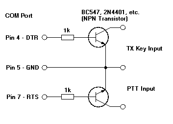
If you have a simple transistor-based COM port CW interface (see below), you can enable this by again choosing the corresponding COM port, and selecting Other interface... from the drop-down list. Clicking on the Configure button will display the COM Port Properties dialog including a drop-down list of options for DTR (pin 4) and RTS (pin 7) on
a DE9 connector (pins 20 and 4 on a DB25). Connect the emitter of the NPN transistor to signal ground, pin 5 on DE9 (pin 7 on DB25).
Be sure to select DTR: CW and RTS: PTT in the COM port Properties under Interface Configuration.
This interface was designed for K1EA's CT and is still in use today with Win-Test.
LPT-port CW keying
Likewise, if you have an LPT (parallel) port CW interface (see schematics below), you can enable it by checking the box next to 'LPT' in the Configure interfaces dialog. Clicking on the [Configure] button in the Printer Ports section will display the Printer Ports dialog. At the very bottom, you can enable CW and PTT on pin 17 and 16 respectively. Ensure this is checked.
WARNING: In order for LPT keying to function correctly under Windows XP, Vista, or 32-bit Windows 7, you will need an additional utility, DLPortIO.dll installed by Port95NT.exe, obtainable from the Win-Test website. It is a simple process and only needs to be installed/run once. Please click here to download. For 64-bit Windows 7, use InpOut32.dll as described in this post.
Digital Voice Keyer
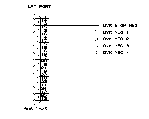
The DVK-100 voice keyer was the first computer-controlled voice memory in the contesting world in the early 90s. Later, some equipment manufacturers built voice memories into their radios like Kenwood (TS-850, TS-950 with the DRU2 and DRU3 units respectively - probably others). These devices can be controlled by Win-Test using the following LPT interface.
Usually the device has 3-4 different memories which can be triggered by [F1]...[F4] on the computer keyboard.
Sound Card
Wav files can also be played from an internal sound card by utilizing a small interface like shown below. Messages are recorded using Shift-F1...Shift-F7.
The use of an isolation transformer is recommended both on the output side of the sound card. Of course, you can go without one but first think about the trouble you will encounter when the Line Out port of your sound card gets killed by stray RF or when someone tells you you got hum on your audio in the middle of the contest.
W9ZRX has provided this design that comes without a relay to switch Mic input between radio and sound card. Most sound cards allow routing from Mic input to Line Out so that you can control muting Line Out from within Win-Test. Make sure that the Microphone has been enabled as an Input to the Sound Card Mixer. Different Sound Cards set up slightly differently, but most seem to either show the Microphone Input to the Mixer as muted, or the default Mixer Inputs do not include the Microphone until enabled.
There are sound cards that do not support this option. The Writelog download site has a sound card checker that will help you to determine if you have this problem if it absolutely doesn't work.
Another way would be to try using the Win-Test PTT output to drive a relay to allow a direct routing between your Mic and the Mic input of your TRX when the PTT output is off. This requires some additional components but better than an external mic to record the DVK messages.
Band Data
Win-Test supports filter and antenna switching by supplying Yaesu-standard Band data on pins 2, 7, 8 and 9 of the parallel port. These pins are equivalent to lines A, B, C and D. This feature allows you to automatically control other devices in your station, probably by using a band decoder like the one from Top Ten Devices.
| Band | A | B | C | D |
|---|---|---|---|---|
| 160 m | 0 | 0 | 0 | 1 |
| 80 m | 0 | 0 | 1 | 0 |
| 40 m | 0 | 0 | 1 | 1 |
| 30 m | 0 | 1 | 0 | 0 |
| 20 m | 0 | 1 | 0 | 1 |
| 17 m | 0 | 1 | 1 | 0 |
| 15 m | 0 | 1 | 1 | 1 |
| 12 m | 1 | 0 | 0 | 0 |
| 10 m | 1 | 0 | 0 | 1 |
| 6 m | 1 | 0 | 1 | 0 |
| 2 m | 1 | 0 | 1 | 1 |
| 70 cm | 1 | 1 | 0 | 0 |
Radio 1/Radio 2
LPT pin 14 is used to send Radio1/2 information to an external interface. High = Radio1, Low = Radio2.
Headphones Control
The signals Headphones Control (called RX Focus in the MK2R microHAM SO2R interface) is available on LPT, pin 4. This signal allows to control which radio you want to listen to in the headphones. Must be enabled in the LPT Configuration Window. Low = Radio 1, High = Radio 2.
See Also
From the Win-Test manual
- Configure interfaces dialog
- Networking configuration for multi-ops
- EZMaster setup
- microHAM MK2R setup
